
Warning Light Durability
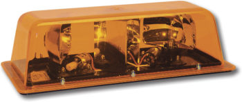
Star Mini-Bars
Warning light durability is having a light that is suited to the vehicles application. Minimum requirements are how the circuit board and lamp components are protected from moisture, vibration, shock, and other features that are required by the fleet.
First and foremost issue with a warning light is its ability to warn the oncoming traffic of an obstruction on the roadway. After accomplishing this task, the environmental impact the warning light is subjected to, will need to be addressed. To assure the product has the ability to meet the requirement of our industry, we again look to the automotive industry’s Society of Automotive Engineers, (SAE).
Years of testing has provided the market with the SAE document, J845 rev DEC 2007 Optical Warning Devices for Authorized Emergency, Maintenance, and Service Vehicles. This is an all-encompassing study for warning lights, including the previous article on photometric performance.
The requirements are:
Vibration tests are described by the frequency of the vibration, the G-Load, the direction of the vibration and test duration after which would not cause any harm to the product.
Moisture/Submersion test are described by the products ability to resist moisture which causes harm to the product.
Dust Exposure is described as the lamps ability to resist dust to a point where it would affect the photometric qualities of the product.
Corrosion is described as salt solutions that is sprayed on the product for duration of time and assures no effect on the performance of the product.
Warpage is described as heat from the product itself in combination with ambient temperature, assuring the heat will not affect the photometric and performance of the product.
By specifying a SAE certified light you can be assured the product has meet these standards for environmental issue.
Increasing reliability is to eliminate the weaker components or better protect them. Technology has provided our industry with enhancements in LED allowing elimination of many of the weaker components in a strobe warning light.
In the past we had to take extra steps to protect the components by stabilizing them on mounting bases isolating them from vibrations. Also because of the amount of energy these components required their size was also restricting. Less power in LED reduces the size of these components therefore providing an easier means to manage the environmental issues.
Improving a warning lights ability to survive the environmental issue can be shifting from Gas-discharge warning light to LED warning lights.
What are the advantages to move from Gas-discharge strobe light to LED warning lights?
There are four high energy components on a strobe light which are not on a LED warning light. These components allow the circuit to build up the energy to create the flash from the strobe light.
The four major components: flash tube, high energy capacitor, the high energy transistor and the coil
All of these components need special attention to assist in providing a longer product life. Warning light designer needs to address the environmental impact for these components as far as, heat transfer, stability of the circuit board, to protect from vibration based on the weight and size of these components. The designer must provide a stable base to mount these larger components to and make sure that the strobe light’s circuit board is not enhanced by any of the vibration produced by the machine to which it is mounted.
Just the weight and size alone is a major difference between a strobe and a LED warning light, as it is related to protecting the circuit board from the major environmental issues. As the flash tube and the capacitor consume themselves the life of the light is destine to fail. In fact with thousands of samples we discovered the flash tube in most cases is always first to fail then followed by the capacitor.
The LED warning light eliminates all four of these larger components, allowing for smaller and lighter circuit board enabling the designer to better protect the lamp from the environmental issues.
LED Specifications that calls out the generation of LED has little purpose. The manufacture must meet the light output requirement of S.A.E. Class I, II or III.
There have been design changes in the development of LED over the years. The LED industry has improved;
- Light output (intensity)
- The spread of the light coming from the LED circuit itself (the direction of the light flowing from the LED fixture )
- Heat management
Common protocol for these changes has been Gen I, our first exposer to LED in the transportation industry. These LED were a great improvement to the incandescent filament as they addressed the key factors of filament brakeage due to vibration and inrush voltage that notched the filament causing failure.
This Gen I LED, were through-hole design, and had a very narrow spread of light emitting from the LED itself. At best, a standard part could achieve an angle of light spread from the LED of 15⁰, 23⁰ or 30⁰. The lamp produced with this Gen I LED, because of that narrow spread, required several LED to meet the photometric light requirements for a vehicle signaling light or warning light. The change from incandescent lamp design with the Gen I LED was the in lens for the lamp fixture. The lens basically became a cover for the product. Meeting the photometric requirements was relinquished to the number of LED and placement in the lamp fixture. This created restrictions by the size of the fixture it was to be placed in and the amount of light needed to meet the photometric requirements. In some cases you need so many LED’s the fixture became too large and the cost of all the LED’s outweighed the advantages of the LED lamp.
Continuing LED development provided the industry with the Gen II. This change increased the light output from the LED and widened the angles of light emitting from the LED to about 100⁰. This generation also gave us surface mounting packages. The Gen II allowed engineers to incorporate lens optics to meet the S.A.E. requirements. Generation III provided the same result adding light intensity and increasing the angles of light emitting from the LED to almost 120⁰. These enhancements will continue to develop and the market will continue to provide more light output LED.
As you can observe by the three examples on the left you can see how the dependence on the LED has changed from needing more LED to using less and relying on the optics in front of the lens to meet the requirement. All three of these lights meet the same light output requirement.
Conclusions are, use an acceptable standard that test the product for light output at the correct angles that meet the light intensity at the test points. Most everything else is simply marketing made specification, like the number of LED and of type LED. Always specify a product that meets the light spread, intensity and the environmental requirements of Vibration, Moisture and Submersion, Dust exposer, Corrosion, Warpage, and Humidity. S.A.E has provided this industry with a standard that assures the market the product has durability and functions to meet the needs for a warning light.